


Trenching Considerations - Pipelines
Ploughing
Ploughs are great tools for making trenches under the following conditions:
- Sands and soft silts (cohesionless soils);
- Cohesive soils up to 5 kPa undrained shear strength;
- Water depths greater than 7 metres;
- Trench depths less than 1.7 metres;
- Pipeline Outside Diameters less than 30"; and
- When the economics of the project allow for a large barge (with a correspondingly large crane and winch) to lift and pull the plough.
Most ploughs are of the post trenching type and have 30° shares that are capable of making 1.5-1.7 metres maximum trench depth. Ploughs typically weigh 130-250 tonnes and require pull forces of 80-220 tonnes, depending on the soils and the trench depth.
Ploughing is fast, with speeds of up to 15 m/min achievable. The required pull force is usually large and mostly independent of the speed. However, ploughs are usually designed for a narrow range of soil properties, and if the soil characteristics change appreciably problems may result.
For example, a wide-bodied plough designed for making trenches with 30° sides (for sands or soft cohesive soils up to say 10 kPa undrained shear strength) may dig a much shallower trench if significantly harder soils were encountered (say 30 kPa undrained shear strength).
To accommodate harder soils, ploughs can be made longer with a heavier share, or they can have a narrow-bodied share. But there are practical limitations on the pull force and the expenses associated with handling and fabricating such a heavy plough. A narrow-bodied plough or heavy plough could sink excessively in the seabed if there is an insufficient bearing area on the front skids and share. Also, with a narrow-bodied plough, an unstable trench may result in sand or soft soils.
In very shallow water depths, ploughs are only partially submerged and the increased weight creates a large increase in the pull force required. So ploughs are generally unsuitable in shallow water depths. In addition, most large barges with suitable cranes are unable to operate in waters less than 7 metres deep.
A 30° trench slope sand plough developed for Woodside Petroleum weighed 300 tonnes and trenched a 40" diameter pipeline in a 1.7 metre deep trench with a pull force of 400 tonnes. Problems resulted when soft silty soils were encountered, requiring the front skid plates to be enlarged. Also, the plough was unable to dig more than 200 mm deep into the limestone sections.
Recently off the Chinese coast, one plough failed to successfully trench in soft silts. For this project the plough share needed to have and angle of 20°, or the plough needed to be pulled very slowly to prevent silts sloughing back into the newly cut trench. Another plough also failed in Vietnam on the White Tiger Project in 30 kPa undrained shear strength clays with a 220 tonne pull force.
A 20 metre long plough designed to make a 30° trench slope in soft cohesive soils (5-10 kPa shear strength) was used on the 20" diameter Maui A-B Pipeline. The plough weighed 220 tonnes and trenched a 2 metre deep trench with a pull force of 60 tonnes. During operations the plough became stuck several times, and when freed it would lunge forward (approximately 80 metres) because of the elasticity in the tow line. The Client was very concerned by this and refused to allow it to be operated near the platforms. Consequently, jetting methods were used close to the platforms. The problem with the elasticity of the tow line can be almost eliminated by using a chain to tow the plough. OES successfully first introduced this method on a project for Woodside Offshore Petroleum.
When a wide range of soil strengths occur along a pipeline route, more than one plough may be required to successfully trench the entire pipeline length. For example, one plough for the softer soils (say 1-30 kPa undrained shear strength) and one plough for harder soils (say 30-70 kPa undrained shear strength) may be required. Alternatively, a jet or sled trenching machine may be used in the harder soils. Also, the mobilisation and demobilisation costs of a large plough and the associated large barge is very expensive compared to the smaller jet trenching machine and smaller support vessel.
Jetting
Jetting is a term used to describe a system that employs water jets to cut or liquefy the soils around and in front of a pipeline. The soils are removed by air lifts, water eductors or submersible pumps. The jetting device can be stabilised by skids that slide on the seabed (a "jet sled") or by buoyancy tanks on a machine that rolls along the pipeline (a "jet machine"). OES has developed, and successfully utilised, a new concept where a jet machine (which rolls along the pipeline) is stabilised by a lead keel.
The effect of the type of soils encountered when using jet trenching methods are described below.
a) Cohesive Soils
Generally in cohesive soils, if the jetting pressure to soil shear strength ratio is doubled the jetting speed is doubled. For example, the trenching speed in 40 kPa undrained shear strength hard green clay may be 2 m/min @ 1,000 psi. If the soils change to 15 kPa undrained shear strength clay and at the same jetting pressure, the trenching speed can be 4 m/min. Alternatively, if the soils become 100 kPa undrained shear strength the trenching speed can drop to 1.5 m/min @ 1,000 psi pressure.
b) Cohesionless Soils (Loose Sands and Silts)
Cohesionless soils (loose sands and silts) are generally easy to cut and only require low jetting pressures (say 130 psi). However, it is often difficult to trench these soils because a very shallow trench slope (20°-30°) is required for the trench to remain stable and not infill behind the trenching machine. It is also important that the soils removed from the trench are deposited sufficiently far enough away so that they do not infill the trench before the pipeline touches down.
In 8-40 metre water depths, the use of air lifts is a very effective method to remove the soils from the trench. For water depths less than 8 metres, water eduction methods are generally better.
In very shallow water (less than 4 metres), a small pontoon barge can be used to support the trenching machine. A pump is placed on the pontoon barge to supply water to the jet nozzles and the water eductors. The trenching speed is limited and the number of passes required is high due to the limitations on the capacity of the eductors to remove the soils. For example, for a 2 metre deep trench in sand (30° trench slope required) or say a 15 m2 trench cross section in sand where 5 m3/min of sand slurry can be sucked up through the eductors, the trenching speed is limited to 1 m/min and 3 passes are required.
In deeper water, the trenching speed is higher and the number of passes required is reduced. For the 2 metre deep trench example above with sufficient air volume flow rate available, the trenching speed can be 2-3 m/min with only 2 passes required.
c) Shelly Clays
During jetting, if a very high percentage (say 40-70%) of shells exist in a clay matrix, then during jetting the soils behave as if the clay is much stiffer than the same clay without any shells present. Therefore, a higher jetting pressure is required or a slower trenching speed results. This is because the water from the jets is unable to cut the clay matrix behind a shell until the shell is loosened and falls away. The strength of the soils can be increased by up to a factor of 6-10 depending on the amount of shells present.
A brief description of the two main types of jet trenching machines is presented below.
a) Jet Sleds
Jet sleds were the first type of jetting device used. They slide along the seabed on skids and the skids need to be sufficiently wide enough to be able to span across the trench. So for cohesionless soils (sands and silts), where a shallow trench slope is required for stability, jet sleds need to be very wide. For example, a typical jet sled would be 10 metres wide and weigh 25-30 tonnes and require a pull force in the order of 40 tonnes to trench a 2 metre deep trench on sand.
Due to the relatively high machine weight and large pull force required, jet sled usually require a large barge with a large crane to deploy and pull it. The relatively large barges required generally have enough deck space for a lot of pump power (eg. 2,000 psi @ 10,000 USGPM). With such high pressures and flow rates, jet sleds can cut hard clays (up to 120 kPa undrained shear strength) and can create up to 2 km of 2 metre deep trench in clays.
However, the mobilisation and demobilisation costs of large barges is high and they are generally unable to operate in water depths less than 7 metres.
Two other problems with jet sleds include 1) interference of the sled skids in allowing the jets to blast the sand away and 2) the liquifaction and consequential sloughing in of a sandy sea bed into the trench behind and after passage of sled skids.
b) Jet Machines
Jet machines are much smaller and lighter than ploughs and jet sleds. They are typically 4-6 metres long, weigh 3-9 tonnes and require pull forces in the order of 1-5 tonnes.
Jet machines roll along the pipeline and are usually stabilised by buoyancy tanks. OES have developed and successfully utilised a unique lead keel jet machine concept that has a low centre of gravity. Jet machines can either be pulled or they can be self propelled. Self propulsion can sometimes be an advantage when trenching near offshore platforms. However, self propelled jet machines generally have more mechanical downtime due to propulsion problems, including fouling of the drive motor on anodes, field joints and debris.
Mechanical Cutters
In general, mechanical cutters have only been successfully used as post trenching machines in soft cohesive soils. They are not very efficient in sand, unless they have good spoil removal system. For example, one company had a mechanical cutter that could only operate on 6 kPa undrained shear strength soils and so they used OES's lead keel jet machine when 30 kPa undrained shear strength soils were encountered.
Generally, mechanical cutters are not able to cut a trench directly underneath a pipeline due to the high risk of damaging the pipeline. For the pipeline to rest in a trench, it must break through the soil which it is not always able to do. As an alternative, two contractors have developed systems that cut a trench to the side of the pipeline which depends on the pipeline being able to deflect laterally back into the hole.
Mechanical cutters are able to trench in rock up to 50 MPa (50,000 kPa) unconfined compressive stress (UCS), which is 500 times harder than typical hard clays (up to 100 kPa undrained shear strength). One company has been successful in developing a rock saw chain trenching machine. However, this machine has to make a pre-trench, and there is the potential of the trench filling in with sand before the pipeline is laid.
OES have developed two mechanical cutter machine concepts that can jet sands and clays and cut rock to 70 MPa UCS. With one system, the pipeline is raised up from the seabed and the cutters cut underneath the pipeline. As the cutters move forward the pipeline settles into the newly cut trench behind the machine. The second system “Rock Eater” involves four cutters and is for larger diameter pipelines around 42” to 48” diameter.
Pre-dredging
Pre-dredging usually involves the use of a cutter suction dredge, although a bucket dredge or clam shell is also sometimes used, to pre-trench shore or near shore crossings.
In this mode a very wide and very deep pre-trench is made to allow for barge passage and some backfill prior to pipe placement. The trench is usually very wide, 20 to 30 metres, as a result of the swing pattern of the dredge ladder that pivots about a fixed point towards the bow of the dredge barge.
Often in very shallow water some pre-dredging may be necessary so the lay barge can get in close enough to shore to either pull the pipe towards the shore if it is welded from the barge or from shore if the pipe is welded together onshore.
If rock exists along the pipe route, pre-dredging may be an advantage in the absence of a proven sub sea post rock trenching machine which is still in developmental stage in 2001.
Pre-dredging shore crossings is an environmental disaster as large quantities of soil and sometimes coral are removed causing complete destruction to the seabed life, long term alteration to the beach profile and enhanced erosion. Total destruction to seabed life and fish from the deposition of the dredged material also occurs.
Pre-dredging is also very expensive, many times greater than post trenching methods. Often the entire exercise is a waste of money as heavy seas can fill in the trench prior to pipe placement.
OES has already salvaged two projects involving five pipelines, namely Pinghu China in 1998 and Cantarell Mexico in 2000 that were pre-dredged but the trench filled in prior to pipe placement.
Directional Drilling
Directional drilling was first pioneered in the late 1970’s and was successfully used to drill a small diameter land pipeline crossing of the Houston ship channel. It worked well as it does for small diameter pipeline river crossings. In this mode, the pipeline exists up out of the river bank at an angle of twenty to thirty degrees and can easily be cut below the ground in the dry and a bend welded on to continue the pipeline in the horizontal direction.
In recent years, under the belief this is an environmentally preferred method to opening the dunes, it has been used only with moderate success to install offshore pipeline shore crossings. As the pipeline increases in diameter above 200 NS, the stiffness and weight of the pipeline requires larger installation equipment and a much longer drilling length.
One of the biggest problems is the pipeline exit angle at the sea bed. This angle needs to be reasonably steep, say greater than ten degrees, otherwise the hole will not be maintained and it collapses. With the hole collapse, the entire pipeline can be stuck and lost as has happened in previous projects. Hole collapse can also happen even at steep angle departures. If the pipeline does exit the sea bed safely and no collapse and loss of pipe or loss of deadly caustic drill fluid has happened, there is yet another major problem - what to do with the pipeline that protrudes out of the sea bed rather than exiting parallel and following the sea bed. It is not feasible to cut and weld a bend under water as it is on land and so the result is usually a large overstressed pipeline span at the sea bed which needs to be post trenched anyway.
In 1997, OES successfully post trenched down 4 metres to uncover the Sabah Gas Pipeline directionally drilled pipeline and then jetted further out to lower the existing pipeline and reduce the pipeline bending stress to acceptable levels.
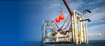
OES's Lead Keel Jet Trenching Systems
a) Shallow to moderate water depth version (1m to 100m)
OES have developed and successfully operate four lead keel jet trenching systems. These machines have many advantages over ploughs, jet sleds and jet machine stabilised with buoyancy tanks.
OES jet trenching machines can be operated from small barges and supply boats, thus they are ideal for shore approaches in very shallow water. They are suitable for both sands and clays up to 190 kPa undrained shear strength. For economic reasons, they are suitable for trenching near offshore platforms, for short pipelines (less than 30 km long) and for large pipelines (>30" OD) where very deep trenches are required (>1.7 m). In comparison, typical ploughs and jet sleds are unable to trench, or they are not economical to use to trench, pipelines under the above conditions. The larger barges required are more expensive, require 8-10 times the power and cannot operate in very shallow water depths. Also, jet sleds with buoyancy tanks are not able to operate in very shallow waters where the tanks are exposed to the air.
The OES jet trenching technology result in machines that are much smaller and lighter that jet sleds and ploughs. They are 3-6 metres long, weigh 3-9 tonnes and thus require lower pull forces. They can also be operated in deeper water from a small DP vessel.
The OES machines are capable of making very deep trenches with multiple passes because they roll along the pipeline and do not span the trench width like jet sleds do. A 5 metre deep trench has been made in sands with an OES machine at the shoreline. For this project, an equivalent jet sled would have had to have spanned at least a 20 metre wide trench, making it very large and heavy. Ploughs are unable to make more than one pass, so they are limited to a maximum of 2 metre deep trenches.
Also, the OES trenching machines are able to trench a wide range of pipeline sizes (up to 54" OD). Most ploughs are limited to a maximum pipeline OD of 30".
OES trenching machines are also generally more stable than jet machines stabilised with buoyancy tanks in strong currents or in large waves. This is because the lead keel concept results in a low centre of gravity and there are no buoyancy tanks to create a high current drag on the machine.
b) Deep water version (100m to 400m depth)
OES have pioneered another major innovation in that they have extended the water depth capability of their lead keel machines by adding deep water hydraulic powered subsea jet pumps as used successfully on their Tiger Prawn II jet sled. OES also improved the suction capacity of Tiger Prawn II for the lead keel machines by adding subsea hydraulic powered double intake/volute centrifugal pumps for soil eduction.
The new eduction system is much more energy efficient than the water eduction system which OES normally use quite well for surface supplied water. The increased efficiency, however, is necessary for deep water and a 100% increase in flow rate has been achieved.
Back to the top